


What is a PLC?
A PLC, or a programmable logic controller, is essentially a computer. However, unlike a personal computer, PLCs are specialized and control machines, and processes using logical commands. These miniature CPUs are designed to withstand an industrial environment and to interface flexibly with inputs and outputs within a real-life application.
Using a personal computer as an example, think of how printing a page works. A user inputs a print command, which relays information from the main CPU towards the printer, previously connected via cables, but now travels over WiFi in most homes. This simple concept applies itself to PLCs where they serve as a conduit for an automated task. A user will program the PLC to adhere to certain tasks and then relay those tasks down the production line, which, in essence, is an automation process.
PLCs vary in size and shape, which could be as small as to fit in your pocket or a great controls system requiring several large racks.
PLC components
The PLC rack is important, as it holds everything together. The size is dependent on how many modules are needed for the control system. The backplane of the PLC is reminiscent of the human spine and serves as a way for the cards to communicate with the CPU. Essential for operation, the power supply plugs into the rack and sends regulated DC power to other modules.
The CPU module serves as the brain of the entire PLC system and found in a slot next to the power supply. CPUs can vary by manufacturer but mainly consist of a microprocessor, memory chip, and other integrated circuits needed to control logic, monitoring, and communications. Different operating modes are set to control the PLC. Programming mode accepts the downloaded logic from a PC, which then switches to run mode that the program can be executed, and the operation is processed. As a dedicated controller, the PLC process runs consistently until a new process is selected and then set.
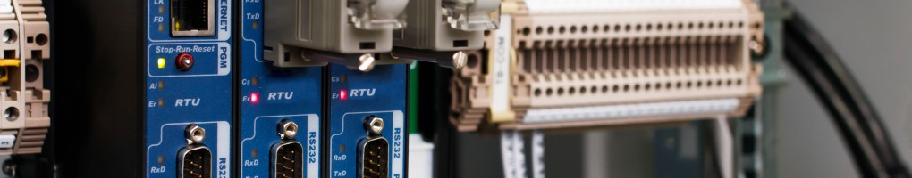
Moving on, the I/O system provides the physical connection between the PLC and the equipment that will become automated. I/O system cards vary based on how the condition type of input or output the CPU uses for its logic. The set up coordinates by determining what inputs and outputs are needed, and then selecting the appropriate cards for those needs.
We’ve touched on inputs and outputs, but now let’s see how they work within a PLC. An input or an output refers to the device that the PLC will either control or relay information for the instrument to perform a task. These devices are either digital or analog. A digital device that will act as an input will send out a signal that can either turn on or off a function such as a pushbutton, limit switch, sensors or selector switches.
On the flipside, an analog device will convert a voltage or current into a digitally equivalent number that can then be understood by the CPU. In contrast, an digital output device plugged into a PLC either turns on or off lights, LEDs, small motors or relays. Much like inputs, an output analog will convert a digital number sent by the CPU to it’s real world voltage or current.
PLC Programming
With an understanding of how the PLC physically works, let’s move on to how it’s programmed. The process started with specialized dedicated software provided by a PLC manufacturer and programmed via a PC. Ladder logic is the most widely used form of programming PLCs. Using symbols, instead of words, to emulate the real world, ladder logic relays logic control as symbols become interconnected by lines to indicate the flow of current through relays like contacts and coils. To attain a high level of functionality, the number of symbols increased over the years. When the program completes, the visual representation resembles a ladder, is an electrical circuit.
For the program to be set into motion, it must be downloaded from a PC to the PLC using a special cable connected to the front of the CPU. Once connected, set the CPU to run mode and then it begins scanning the logic and controlling the outputs.
Root-cause analysis is necessary when PLCs discontinue following established programs. When PLCs need repair, it’s imperative to seek repair specialists with years of experience and knowledge. ICR sources and develops talent internally, joining the company often with dozens of years of experience with PLC programming, installation, monitoring and, of course, repairs.
When in need turn to ICR and request an electronics repair quote for your PLC system.